
| Calibration Window | |
This window simplifies the process of entering scale and offset factors, and graphically displays the calibration history of your dataset. To access it, choose from the menu.
Windographer automatically reads calibration constants, and boom orientations and serial numbers if available, from many types of raw data files. If Windographer succeeded in doing so, you can use this window to verify whether it read them correctly and to make any necessary changes. If the calibration constants did not appear in the raw data file or Windographer failed to read them, then you can use this window to enter those values.
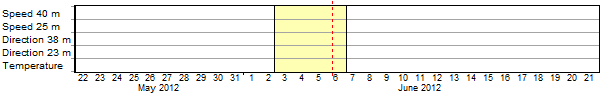
The diagram at the top of the page provides a graphical snapshot of the calibration history of your data set, and lets you click to select calibration periods. The diagram shows one row for every data channel. In the example below, the user has clicked on May 29 (highlighted by the dotted red line) to select the calibration period that extends from May 22 to June 2 for all data channels:

The vertical black line on June 2 indicates that at that time, one or more calibration constants (slope, offset, or serial number) changed for all data channels. In the example below, the user has clicked on June 6 to select the calibration period that follows that change:
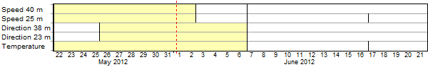
Calibration constants do not always change for all data columns at once. In the example below, the vertical line on May 25 indicates that calibration constants changed at that time for the direction channels only. (That could happen if you replaced the direction vanes without changing the other instruments.) Similarly, the vertical line on June 2 indicates that the calibration constants changed at that time for the speed channels only. The subsequent calibration period is more complex as a result, its extent changing by data channel:

With that same example, clicking on June 1 selects a somewhat different calibration period, sharing some of the properties of the one above, but with different calibration constants for the speed channels:
Below the diagram, the table displays the calibration constants for the calibration period that you have selected. The background color of the table matches the color of the selected calibration period in the diagram to remind you that the calibration constants apply to that selected period. You can modify the scale/offset values and, if you wish, enter the serial number of each instrument.
From the Tables window, the Calibration History table provides a single table with this information. Any change in calibration, serial number or boom orientation is shown as an additional row of information.
To create a new calibration period, click on the diagram at roughly the correct time, then use the date/time controls at the left of the table to specify the start time precisely. Then click Create New Calibration Period Starting Here and make the necessary changes in the table.
If you have created a calibration period in error, or you wish to remove a calibration period for any reason, you can use one of two methods to merge calibration periods. The first method is to set the constants for one calibration period equal to the adjacent calibration period, which you can do by copying the table from one period and pasting it into the adjacent period. When you click OK, Windographer will merge those two adjacent calibration periods because it will recognize that there is no distinction between them.
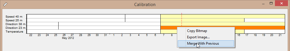
The second method is right-click on any segment in the diagram and choose Merge With Previous. That will cause Windographer to set that data column's calibration constants in that time interval to those in the previous time period.
If you modify scale or offset values, you can choose whether you want Windographer to recalibrate the affected data points, or simply to store the calibration constants. If you import raw uncalibrated data and then use the Calibration window to enter the scale and offset values, you definitely want the change the data points so you would choose the radio button labeled Store these constants and apply them to the data.
But if you are working on a dataset that has already been calibrated and you are using the Calibration window simply to store the calibration constants that you have already applied outside of Windographer, then you do not want to recalibrate the data, so you would choose Store these constants but don't change the data.
If you do choose to apply the calibration constants, then Windographer will modify the affected data points by, effectively, factoring out the previous scale and offset values, and then factoring in the new scale and offset values. (The factoring out of the previous calibration constants is necessary because Windographer stores only the calibrated values, not the uncalibrated values.)
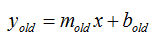
To derive the relevant equation, we will start with the equation relating the uncalibrated data, for which we will use the symbol x, to the calibrated data, for which we will use the symbol y, with the calibration constants that applied before the change:
After changing to the new scale and offset values, the calibrated and uncalibrated values will be related by this equation:
Solving the first equation for x and substituing into the second equation, we find the equation that Windographer uses to account for a change in the calibration constants:

From the Tables window, the Data Channel Summary report shows all of the wind speed and wind direction columns along with the calibration, serial number and boom orientation. The Calibration History table is also available in the Tables window.
See also