
| Boom Orientation | |
Anemometers and wind vanes mounted on a meteorological tower are typically mounted at the end of a horizontal boom with a length of 2m or more. Mounting an instrument at a distance from the tower insulates it from the worst of the distorting effects that the met tower has on the wind flow.
The boom orientation is the azimuth of the boom when viewed from above. A boom orientation of 0° corresponds to a boom that points due north from the met tower. A boom orientation of 90° corresponds to a boom pointing due east, 180° due south, and so on.
Boom orientations can change over time, sometimes because of small inadvertent shifts that may occur when towers are tilted down for maintenance. For this reason they resemble calibration constants that can also change in time, and as a result they appear in the Calibration window in Windographer.
As an example, imagine an anemometer mounted on a met tower at a boom orientation of 135°, meaning southeast. The diagram below shows the position of that anemometer relative to the met tower, from the perspective of looking down at the tower from above. The orientation of the boom is 135° clockwise from due north:
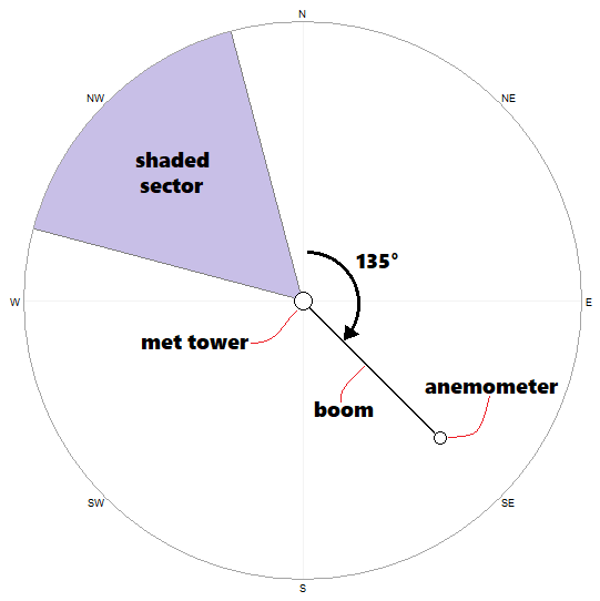
Note that the purple sector in the diagram above indicates the 'shaded sector', meaning the range of wind directions over which our example anemometer would experience tower shading. The center of the shaded sector is always 180° away from the boom orientation because wind direction refers to the direction from which the wind blows. (Here we have assumed a width of 60° for the shaded sector; some analysts assume larger shaded sectors, some smaller.)
Tip: Boom orientations apply to meteorological towers only. In other types of datasets, such as SoDAR or LiDAR data, or computer modeled datasets such as MERRA-2, leave the boom orientations at zero.
Windographer uses boom orientations in the Flag Tower Shading window, making the flagging of tower shading very easy. It knows that an anemometer experiences tower shading whenever the wind direction is roughly 180° from the boom orientation. So even if the boom orientation changes over time, you can flag all tower shading events in just a single click in that window.
Windographer also uses boom orientations in the Tower Distortion window. The graphs that appear in that window highlight the expected center of the shaded sector, so that you can see how well that agrees with the observed shading patterns.
Specifying boom orientations also enables the combination of co-located anemometers by boom orientation, using the IEC rule of thumb that the optimal boom orientation is 45° away from the wind direction for tubular towers, or 90° in the case of lattice towers. The Combine Anemometers window offers this option.
See also