| Turbine Spacing Window |  |
The Turbine Spacing window calculates the minimum upwind separation required in each direction sector to satisfy the requirements of IEC 61400-1 4th edition (2019) standards.
You can access this window by choosing from the menu.
Start by choosing a data column to represent hub-height wind speed, a direction column to define direction sectors, and a number of direction sectors. This module will then calculate for every direction sector and every wind speed bin the mean turbulence intensity (TI) and standard deviation of TI in each bin. From those two values it calculates the representative TI in each bin using the following equation:

where: | ||
| IP90 | is the representative TI, meaning the 90th percentile of TI values in the bin | |
| Imean | is the mean of the TI values in the bin | |
| ISD | is the standard deviation of the TI values in the bin |
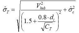
The representative TI represents the ambient turbulence intensity, not including any additional turbulence that may be induced by turbines upwind of the measurement location. To estimate the effect on turbulence of upwind turbines, Windographer uses the equation given in Annex E of the IEC 61400-1 4th edition standards (2019):

where: | ||
 | is the representative standard deviation of wind speed due to ambient and wake-induced turbulence | |
 | is the representative standard deviation of wind speed due to ambient turbulence alone | |
| di | is the distance in rotor diameters to the nearest upwind distance in direction sector i | |
| CT | is the thrust coefficient of the upwind wind turbine |
Windographer calculates  by multiplying the representative TI by the
hub-height wind speed, since those variables are related according to the following equation:

For the thrust coefficient, Windographer uses the simple default relation suggested by the IEC standards:

where c is a constant equal to 1 m/s.
Finally, Windographer divides  by the hub height wind speed to calculate
the effective turbulence intensity, which comprises both ambient and wake-induced turbulence:

In all the equations above, for the hub height wind speed Windographer uses the midpoint speed of each wind speed bin.
If you specify the upwind spacing, Windographer will assume that in each direction sector, a wind turbine exists at that distance upwind of the current location. If you choose instead to minimize the upwind spacing, then in each sector Windographer will find the minimum upwind spacing that keeps the effective turbulence below the Normal Turbulence Model curve for the class you have chosen. In other words, it will find the smallest value of di in each sector that avoids violating the IEC standards.
In performing this search, Windographer begins by setting di to 2 rotor diameters in each sector. Then if the effective TI in any relevant wind speed bin exceeds the representative TI given by the IEC turbulence class at that speed, it increases the value of di by 0.1 rotor diameters at a time until the violations stop or until di reaches 10 rotor diameters. A relevant wind speed bin is one whose midpoint falls within the range of speeds you have chosen to include, and whose TI occurrences are equal to or greater than the minimum number of occurrences you specified.
The filter settings controls allow you to focus the analysis on a subset of your data -- a particular year, a particular temperature range, or any other subset that interests you.The article on filtering data provides details.
Right-click any graph to change its properties, copy the image to the clipboard, or export it to a file. Right-click on any table to export it to a file, or copy it. See the article on exporting graphs or exporting tables for more information.
See also
Representative turbulence intensity