HOMER Pro 3.16

Type: |
Input Variable |
Units: |
% |
Symbol: |
fh |
The pipe head loss is the frictional loss in the hydro pipeline, expressed as a fraction of the available head.
Water (like any viscous fluid) flowing through a pipe experiences a loss in pressure due to friction. We can express this pressure loss in terms of a loss of head, where head is the vertical drop through which the fluid flows. In HOMER, you specify the pipe head loss as a percentage of the available head.
Small high-head, low-flow hydro systems typically experience pipe head losses of between 10% and 20%. With low-head systems, pipe head losses are typically only a few percent.
The head loss percentage is defined in terms of the absolute head loss hl and the total available head h:
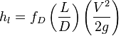
The Darcy–Weisbach equation can be used to predict frictional losses in a circular pipe:
where: |
|
|
|
hl |
= Absolute head loss due to friction, given in units of length |
|
fD |
= Darcy friction factor |
|
L |
= Pipe length |
|
D |
= Pipe diameter |
|
V |
= Flow velocity (where Q-dot is volumetric flow rate): |
|
|
|
|
g |
= Gravitational acceleration (i.e. 9.81 m/s2) |
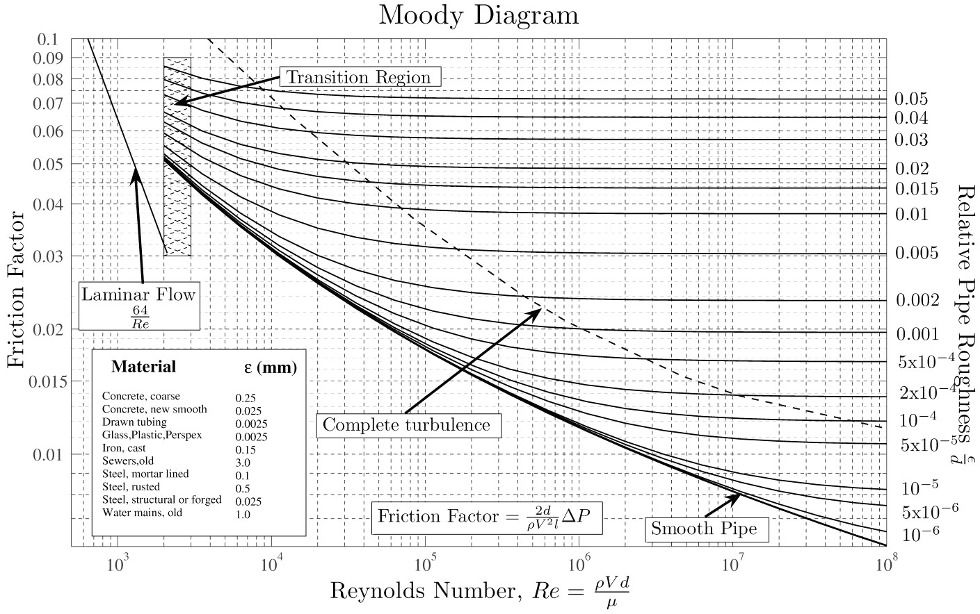
The Darcy friction factor fD can be calculated several different ways, including the well-known Moody diagram (below) or one of many on-line calculators. For laminar flows (Reynolds number, Re, less than 2300), you can use the following:
fD = 64/Re
The friction factor can vary for transition flows (2300 < Re < 4000), and a number of correlations are possible. The Moody diagram provides a good estimate in this method. For turbulent flows, the Moody diagram is a good reference, or you can compute fD by solving the Colebrook–White equation:
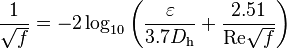
where: |
|
|
|
? |
= Roughness height |
|
Dh |
= Hydraulic diameter (inside diameter for circular tubes) |